- Info.
- Products
Digital Wireless System
Integrated Conference System
Wired Microphone
Audio Assistance - Kits
- XDC236 Series
- Products
- Products
- Components
Analog Wireless System
Wireless Conference System
Antenna
Acessories - Kits
- WDC210 Series
- Products
- Components
- Components
Digital Wired Conference System
- DC190 Series
- Others
Demonstration of Audio Signal Mutil-Order Intermodulation Interference
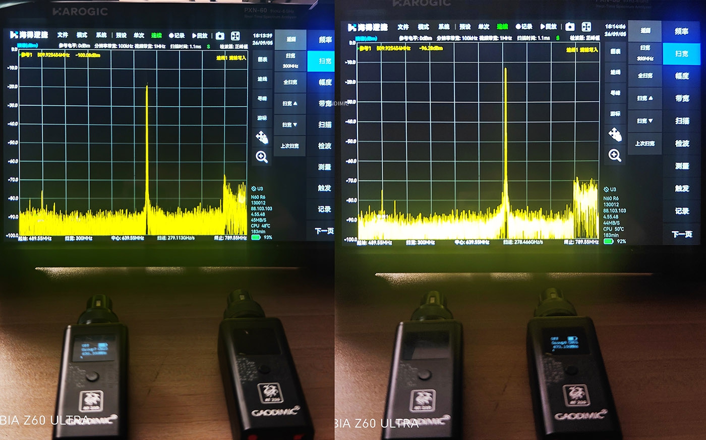
1. working with single signal individual, there is no any interference.
TX1 Working Frequency : 656.350 Mhz
TX2 Working Frequency : 673.150 Mhz
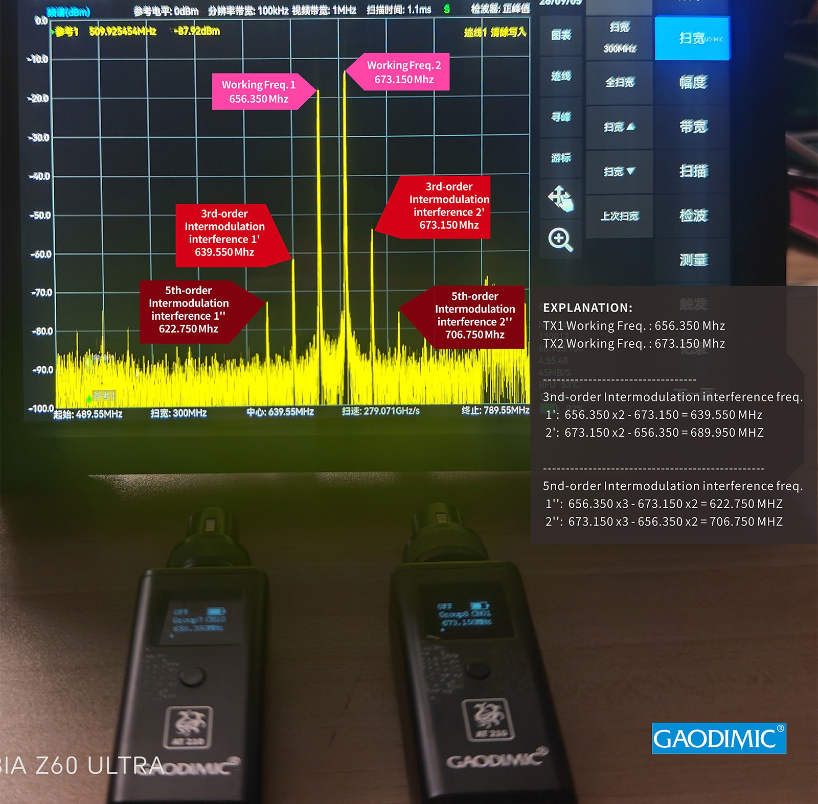
2. Calculation of Intermodulation Interference
----------------------------------------------------------
3nd-order Intermodulation interference frequency:
interference 1': 656.350 x2 - 673.150 = 639.550 MHz
interference 2': 673.150 x2 - 656.350 = 689.950 MHz
----------------------------------------------------------
5nd-order Intermodulation interference frequency:
interference 1': 656.350 x3 - 673.150 x2 = 622.750 MHz
interference 2': 673.150 x3 - 656.350 x2 = 706.750 MHz
3. Relationship between Transmitter Distance and Intermodulation Interference
Relationship between Transmitter Distance and Intermodulation Interference
In short, transmitters should not be placed too close together, as this easily leads to intermodulation interference.
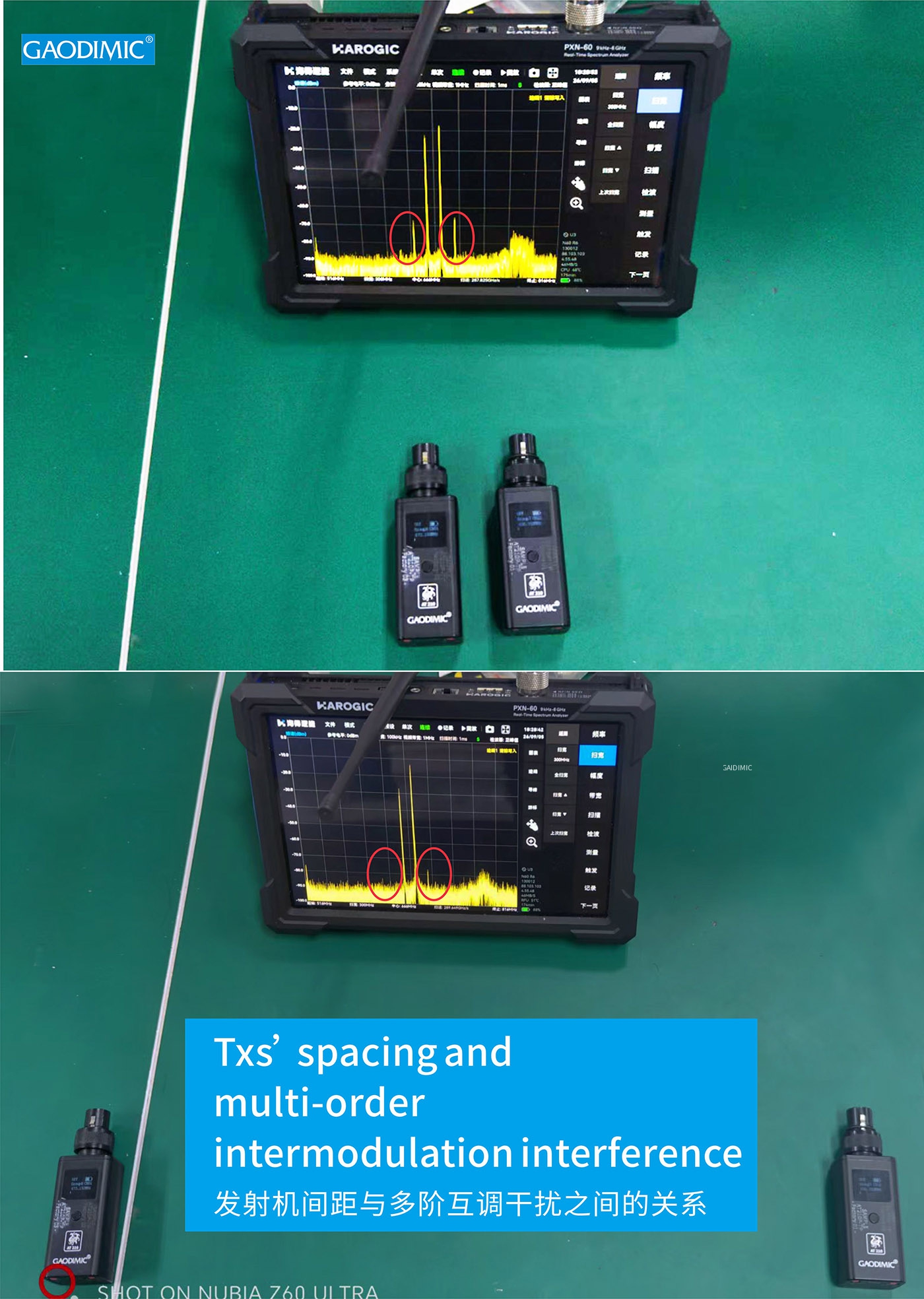
If transmitters must be placed very close, try to use frequencies that are as far apart as possible.
For example:
TX1: 500MHz
TX2: 600MHz
Then the 3rd-order intermodulation interference would be:
500 x 2 - 600 = 400MHz
600 x 2 - 500 = 700MHz
The intermodulation interference would then fall outside the operating frequency band.
4. How to Combat Intermodulation Interference
Intermodulation interference is caused by the nonlinearity of devices. When two electromagnetic waves (trigonometric functions) superimpose, the peaks and troughs overlap, causing amplitude amplification that exceeds the linear operating range of the device. This results in "peak clipping," distorting the electromagnetic wave's nature and introducing waves of other frequencies.
(Numerically, this involves adding two trigonometric functions, expanding using Taylor series, and then determining the higher-order part of the expansion.)
For analog wireless communication, the only solution is to improve the quality of system components, using high-precision components to enhance linearity.
However, for digital wireless communication, the anti-interference capability of the wireless system can be improved through techniques such as orthogonal coding (CDMA), adding calibration codes, or orthogonal frequency splitting (OFDM).
Intermodulation interference is unavoidable in engineering; all methods only raise the threshold for interference. Once the capability is strong enough, all methods of digital communication will be overcome.
The simplest solution: maintain sufficient distance between transmitters.
TEL : (+86)18665358040
Email : sales@infosvc.biz
Facebook : @GAODIMIC | Ins : @GAODIMIC



infoSVC Co., Ltd Tradmark @2026